
Robotic Hardware Parts: A Sourcing Guide for Arm Builders and Integrators
A six-axis arm rated for a 20 kg payload can still miss its programmed pose by 0.2 mm because one bracket came off the machining center 0.15 mm thin at the mounting face. Nothing on the datasheet catches that. The error surfaces months later, as rework on a welding cell or a vision system that needs teaching again every Monday morning. Robotic hardware parts look minor next to reducers and servos, yet they decide whether the arm behaves the way the simulation promised.
Where robotic hardware parts lose accuracy
Repeatability complaints usually trace back to three places: the datum on a welded frame, a joint face machined before stress relief, and a bolt pattern drilled on a drill press instead of a machining center. A welded steel pedestal can move 0.3 mm from welding heat, then move again after the first cut releases residual stress. Buyers who insist on normalizing or vibratory stress relief between welding and final machining pay perhaps 10 percent more and skip the entire argument later. The second common failure is datum shift. If the drawing calls out a bore as datum A but the shop fixtures the part from an outside edge, every downstream feature inherits the shop's convenience rather than the designer's intent.
The part families that carry most of the load
Most of the mass and nearly all of the stiffness in a robot come from a short list of parts: base and pedestal plates, joint housings with bearing seats, reducer adapters, wrist flanges, end-effector mounting plates, cable and hose brackets, and the safety fence hardware around the cell. Of these, the joint housing and the wrist flange deserve the tightest control, because any angular error there is multiplied by the arm length. A 0.05 degree tilt at the wrist becomes 1.7 mm of positional error at a 2 m reach. Cable brackets sit at the other end of the scale. They can be laser cut and bent to general tolerances, and spending money on them is a waste.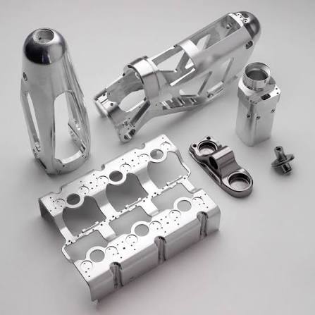
Tolerances worth paying for
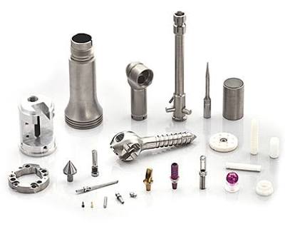
General tolerances to ISO 2768-1, medium class, are adequate for covers, guards and cable trays. They are not adequate for a bearing seat or a mating flange. Practical callouts for a robot joint include a position tolerance of 0.05 mm on bolt circles, flatness of 0.02 mm across a mounting face, and perpendicularity of 0.03 mm between the joint axis and the flange face. Geometric callouts should reference either ASME Y14.5-2018 or ISO 1101:2017, and the drawing needs to state which, since the two systems treat some symbols differently. A shop that quotes from a drawing with no GD&T frame is quoting a different part than the one you designed.
Material choice by axis and duty cycle
Aluminum 6061-T6 covers most arm links and housings. It welds, machines cleanly and holds a decent finish. For wrist parts where inertia matters, 7075-T6 gives roughly 60 percent more yield strength at the same density, at the cost of poorer weldability and lower corrosion resistance. Steel pedestals in 1045 or a ductile iron casting make sense at the base, where mass is an asset rather than a penalty. Remember the stiffness gap: aluminum sits near 69 GPa against roughly 200 GPa for steel, so a swap to aluminum for weight savings usually needs a thicker section, and the weight advantage shrinks faster than expected. Titanium 6Al-4V is worth considering only when a wrist part must be both light and stiff, and the budget can absorb a five to eight times higher material cost plus slower cutting speeds.
Finishing for real factory floors
Type II anodizing at 10 to 15 micrometres gives aluminum parts a working surface and reasonable corrosion protection. Hard anodizing, Type III at 25 to 50 micrometres, is the right call for wear surfaces such as rail mounts and locating blocks, though it reduces fatigue strength and must be masked off threads and bearing bores. Steel parts are usually better served by zinc plating with a trivalent passivation, zinc-nickel for washdown areas, or an epoxy e-coat where impact and chemicals both appear. Mask mating faces before any coating. A 30 micrometre powder coat on a joint face is a soft layer that compresses under bolt preload and quietly costs you alignment. In aluminum housings, stainless steel thread inserts prevent galvanic galling and pull-out during repeated assembly.
Questions that separate a factory from a trading desk
Ask who actually cuts the part. A supplier that subcontracts machining cannot control lead time or drawing interpretation, and the answer shows up in your first deviation report. Ask for the calibration status of the coordinate measuring machine and the acceptance test it was verified against, ISO 10360-2 being the usual reference. Ask whether first article inspection follows AS9102 format, whether PPAP documentation is available for automotive programs, and whether material certificates arrive as EN 10204 type 3.1. Then ask the awkward one: what happens to a 50-piece prototype order when a 5,000-piece annual program lands in the same month. A manufacturer running three shifts with spare capacity will answer in specifics. A trading company will answer with adjectives.
References
ASME Y14.5-2018, Dimensioning and Tolerancing. American Society of Mechanical Engineers, New York, 2018.
ISO 2768-1:1989, General tolerances, Part 1: Tolerances for linear and angular dimensions without individual tolerance indications. International Organization for Standardization, Geneva.
ISO 1101:2017, Geometrical product specifications (GPS), Geometrical tolerancing, Tolerances of form, orientation, location and run-out. ISO, Geneva.
Siciliano, B., Sciavicco, L., Villani, L. and Oriolo, G., Robotics: Modelling, Planning and Control. Springer, London, 2010, Chapter 2.
Groover, M. P., Fundamentals of Modern Manufacturing: Materials, Processes, and Systems, 7th edition. Wiley, Hoboken, 2020, Chapters 21 and 22.
ISO 10360-2:2009, Geometrical product specifications (GPS), Acceptance and reverification tests for coordinate measuring machines, Part 2: CMMs used for measuring linear dimensions. ISO, Geneva.
ASM Handbook, Volume 5: Surface Engineering. ASM International, Materials Park, Ohio, 1994.
